How Aerosol Cans Work: Propellant, Pressure & Valves
Guide Contents
- 1. Introduction to Aerosol Technology
- 2. Basic Components of an Aerosol Can
- 3. The Science Behind Aerosol Pressure
- 4. Types of Propellants Used in Aerosol Cans
- 5. How the Aerosol Valve Works
- 6. How Spray Is Generated (Spray Dynamics Explained)
- 7. What Happens When You Press the Spray Button
- 8. Difference Between Bag-on-Valve and Conventional Aerosols
- 9. Common Engineering and Manufacturing Problems
- 10. Safety Mechanisms in Aerosol Cans
- 11. How Aerosol Working Impacts Product Performance
- 12. How Startups Can Select the Right Aerosol System
- 13. Aerosol Manufacturing in India vs Global Practices
- 14. Authoritative External References for Aerosol Technology
- 15. Future of Aerosol Technology
- 16. Complete Aerosol Manufacturing Guidance
- 17. Conclusion: Key Takeaways on How Aerosol Cans Work
Aerosol technology is one of the most efficient and versatile methods of dispensing liquids, foams, gels, and powders. From pharmaceuticals, cosmetics, and household cleaners to industrial lubricants, paints, and agrochemicals, aerosol cans enable precise, controlled, and hygienic product delivery.
Despite their everyday use, the internal working of an aerosol can involves carefully engineered interactions between propellant physics, internal pressure, valve mechanics, and spray dynamics. For startups, students, and entrepreneurs entering aerosol-based product development, a correct technical understanding is essential for safe design, consistent performance, regulatory compliance, and commercial success.
This article provides a fact-based, engineering-level explanation of how aerosol cans actually work—without speculation—covering propellants, pressure behavior, valves, atomization, safety systems, and real manufacturing considerations relevant to India and global markets.
Introduction to Aerosol Technology
What Is an Aerosol Can?
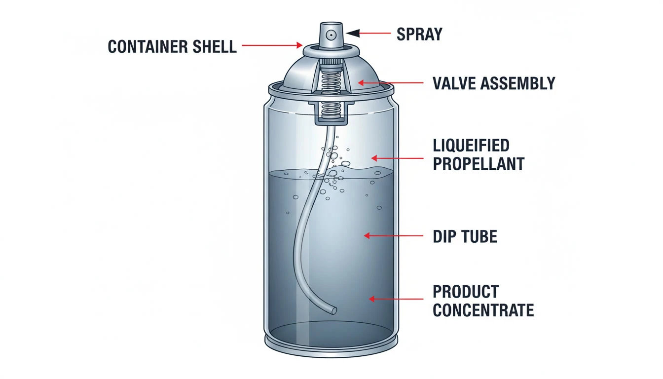
An aerosol can is a sealed, pressurized container designed to dispense a formulation in the form of a spray, mist, jet, foam, or stream using the energy stored in a compressed or liquefied gas propellant. The formulation and propellant are packaged together in a controlled ratio, with dispensing regulated by a precision valve and actuator system.
The entire system functions as a self-contained fluid delivery device where pressure energy is converted into controlled kinetic energy at the nozzle. In technical terms, an aerosol system consists of the following key components:
- A product concentrate
- A propellant
- A valve–dip tube–actuator assembly
- A pressure-resistant metal container
The entire system functions as a self-contained fluid delivery device where pressure energy is converted into controlled kinetic energy at the nozzle.
Where Aerosol Technology Is Used
Aerosols are used in nearly every industrial and consumer sector:
- Pharmaceuticals: inhalers, antiseptics, wound sprays
- Personal care: deodorants, hair sprays, shaving foams
- Household & institutional care: cleaners, insect sprays, air fresheners
- Automotive & industrial: lubricants, degreasers, paints, corrosion inhibitors
- Food & specialty: cooking sprays, release agents
Each application requires a different propellant system, valve design, pressure range, and spray pattern, making aerosol engineering highly application-specific.
Why Understanding Aerosol Working Is Important
For startups and manufacturers, incorrect assumptions about aerosol working commonly lead to:
- Inconsistent spray output
- Valve leakage or clogging
- Can deformation or bursting
- Regulatory non-compliance
- Product performance failures in the market
A technical understanding allows correct selection of propellants, valves, can materials, and filling methods from the very first formulation stage.
Basic Components of an Aerosol Can
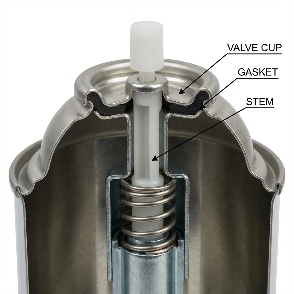
Aerosol valve assembly and crimping seal showing the valve cup, gasket, stem, and metal dome interface.
An aerosol can is not a simple container. It is a pressure-rated dispensing system built from multiple engineered components.
The Can Body (Aluminum vs Tinplate)
The can body provides mechanical strength and internal pressure containment.
Two can materials dominate. Tinplate steel is the most common choice for industrial and FMCG aerosols because it is high-strength, economical, and externally lacquered for corrosion resistance, while aluminium is used mainly in personal care and pharmaceuticals for its seamless construction, better corrosion resistance, lighter weight, and superior surface finish. The full trade-off is set out in our comparison of aluminium versus tinplate aerosol cans.
Typical pressure resistance: 12–18 bar minimum deformation pressure, with burst pressures significantly higher as per international standards.
The Aerosol Valve Assembly
The valve is the control heart of the aerosol system. It seals the pressurized contents and releases the product only when actuated.
It consists of:
- Valve cup
- Internal gasket
- Stem with side ports
- Spring-loaded mechanism (in continuous valves)
- Housing that locks into the can dome via crimping
The Dip Tube
The dip tube is a plastic tube attached to the valve stem that reaches the bottom of the can. It allows liquid product to be drawn upward when pressure forces the formulation through the valve.
Dip tube length and internal diameter directly affect:
- Flow rate
- Spray stability
- Product evacuation efficiency
The Actuator and Spray Button
The actuator is the user-facing spray button. Internally, it contains:
- Expansion chamber
- Orifice(s)
- Swirl inserts (for spray/fog generation)
It is the primary atomization device that converts pressurized liquid into droplets.
Different actuator designs create:
- Fine mist
- Jet stream
- Cone spray
- Foam output
The Propellant System
The propellant provides:
- Internal pressure
- Energy for product discharge
- Atomization force at the nozzle
Propellants are either liquefied gases or compressed gases, and the selection determines nearly every aspect of aerosol behavior.
The Science Behind Aerosol Pressure
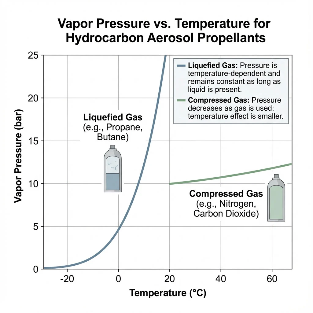
Vapor pressure versus temperature relationship for typical aerosol propellants used in pressurized containers.
What Creates Pressure Inside an Aerosol Can?
Pressure inside an aerosol can is generated by the propellant. It is not created by mechanical compression at the time of spraying. The pressure exists continuously after filling.
Two physical mechanisms are used:
Internal pressure comes from one of two sources: the vapour pressure of a liquefied gas propellant, or the stored gas pressure of a compressed gas. Which one a product uses determines whether spray force stays constant or falls as the can empties, a distinction explored in our guide to compressed versus liquefied gas aerosols.
Vapor Pressure vs Compressed Gas Pressure
Liquefied Gas Propellants
- Exist as both liquid and vapor inside the can
- Pressure remains nearly constant as long as liquid propellant is present
- Example: Butane, Propane, Isobutane, HFC-134a
The physical behavior of liquefied gas propellants ensures a stable discharge throughout the product life cycle. As the formulation is sprayed, the system follows this chemical equilibrium sequence:
- Some liquid propellant evaporates
- Vapor pressure automatically restores equilibrium pressure
- This gives constant spray force over most of the product life
Compressed Gas Propellants
- Exist only as gas inside the can
- Pressure decreases gradually with each spray
- Example: Nitrogen, CO 2, compressed air
These systems show pressure decay, leading to changing spray force over time.
How Temperature Affects Aerosol Can Pressure
Aerosol pressure follows the gas laws and vapor pressure–temperature relationships. As temperature increases, internal pressure increases.
For typical hydrocarbon propellants:
As a working figure, pressure rises by roughly 0.6–0.8 bar per 10°C, so above about 50°C internal pressure can reach unsafe levels. This is the physical reason behind the storage warnings printed on every can, and behind the temperature limits described in our guide to aerosol can safety.
This is why all aerosol cans carry storage temperature limits and undergo thermal stability and hot-water bath testing during manufacturing.
Typical Pressure Ranges in Aerosols
Depending on product and propellant:
- Low-pressure systems (compressed gas): 2–5 bar
- Standard hydrocarbon aerosols: 4–8 bar at 20°C
- High-output industrial aerosols: 6–10 bar
Design pressure is always well below the minimum burst strength of the can for safety.
Types of Propellants Used in Aerosol Cans
Aerosol propellants are the driving force behind the entire dispensing system, dictating not only the internal pressure but also the droplet size and spray pattern. Selecting the correct propellant is a critical design decision that impacts formulation solubility, flammability ratings, and regulatory compliance. Modern manufacturing relies on a variety of liquefied and compressed gases to achieve optimal gassing results.
Liquefied Gas Propellants
Common hydrocarbon propellants:
- Propane
- n-Butane
- Isobutane
- Propane–butane blends
Hydrocarbon propellants are widely used due to their excellent solubility and pressure stability. Manufacturers choose hydrocarbons based on the following physical and chemical properties:
- High vapor pressure
- Good atomization efficiency
- Flammable
- Low cost
- Widely used in India for FMCG and industrial aerosols
Fluorinated propellants (HFCs):
- Non-flammable
- Higher molecular weight
- More stable pressure profile
- Higher cost and subjected to environmental regulations
Compressed Gas Propellants
- Nitrogen
- Carbon dioxide
- Compressed air
Compressed gas propellants offer an environmentally friendly and non-flammable alternative to liquefied gases. They are characterized by the following operational parameters:
- Non-flammable
- Pressure decreases during use
- Used where flammability must be eliminated
- Common in pharmaceuticals, food aerosols, and bag-on-valve systems
Environmental Regulations and Trends
Globally, propellant selection is regulated based on:
- Ozone depletion potential (ODP)
- Global warming potential (GWP)
- Flammability classification
India follows:
- BIS pressure vessel standards
- Petroleum and Explosives Safety Organisation (PESO) norms for hydrocarbon handling
- Globally accepted transport codes for flammable aerosols
How the Aerosol Valve Works
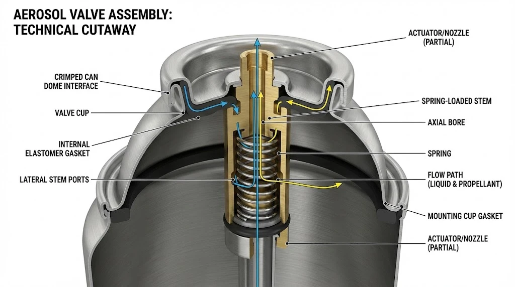
Cutaway view of an aerosol valve assembly showing the valve cup, elastomer gasket, spring-loaded stem, ports, and internal flow path.
Valve Cup, Gasket, and Stem Function
The valve cup is crimped onto the can dome and holds the entire valve assembly. The internal gasket creates a gas-tight seal between the metallic cup and the moving valve stem.
The stem contains:
The stem carries one or more lateral ports feeding a central axial bore, and the size of that restriction is what begins breaking the liquid stream into droplets.
When unpressed, the gasket blocks the ports, sealing the pressurized system. When pressed, the ports align below the gasket, opening the flow path.
Crimping and Sealing Mechanism
During manufacturing, the valve is mechanically crimped onto the can with precise radial compression. Proper crimp diameter and compression force are essential to:
- Prevent leakage
- Maintain long-term pressure retention
- Ensure transport safety
Incorrect crimping is a major root cause of aerosol leakage failures.
Flow Rate Control
Flow rate is governed by:
- Valve orifice size
- Stem port diameter
- Dip tube internal diameter
- Internal valve spring strength
- Actuator orifice design
These parameters are selected based on:
- Product viscosity
- Desired discharge rate
- Spray pattern requirement
Continuous vs Metered Valves
Valves fall into two families. Continuous valves flow product for as long as the actuator is held down and are used in cleaners, sprays, and lubricants, whereas metered-dose valves deliver a fixed volume per actuation for pharmaceutical inhalers and medical sprays. Both depend on the same elastomeric seal, covered in our guide to aerosol valve gasket materials.
How Spray Is Generated (Spray Dynamics Explained)
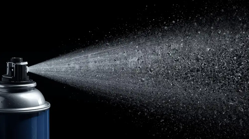
High-speed visualization of aerosol spray atomization and micro-droplet formation at the nozzle.
Formula Movement from Dip Tube to Nozzle
The activation of the spray button initiates a rapid hydrodynamic sequence driven entirely by the pressure difference between the can interior and the atmosphere. When the actuator is pressed, the system performs the following steps:
- The internal valve opens.
- Internal pressure instantly forces liquid up the dip tube.
- The liquid mixture of product and propellant enters the actuator chamber.
There is no pumping action. The system is driven entirely by stored pressure energy.
Atomization Inside the Actuator
Inside the actuator:
- The liquid rapidly expands as it moves from high pressure (inside can) to atmospheric pressure.
- Dissolved propellant flashes from liquid to vapor.
- This violent phase change breaks the liquid into tiny droplets.
This process is known as flash atomization.
Role of Orifice Size and Spray Pattern
The actuator orifice controls:
- Droplet size
- Spray angle
- Delivery rate
Small orifice:
A smaller orifice produces a finer mist at a slower output rate.
Large orifice:
A larger orifice produces a coarser spray or jet at a higher discharge rate.
Swirl chambers and inserts can impart rotational motion to the liquid, producing conical sprays.
Mist, Jet, and Foam Generation
- Mist sprays: High atomization, small droplets
- Jet sprays: Minimal atomization, straight stream
- Foam sprays: Air incorporation through mixing chambers, combined with foaming surfactants
Foam aerosols rely as much on formulation rheology as on mechanical design.
What Happens When You Press the Spray Button
The spray action follows a fixed physical sequence:
- External force depresses the actuator.
- The valve stem moves downward.
- Stem ports open below the gasket.
- Internal pressure forces liquid into the stem.
- Liquid expands in the actuator chamber.
- Flash evaporation of propellant occurs.
- The product exits as a spray, jet, or foam.
As long as liquid propellant remains in a liquefied system, internal pressure remains nearly constant, ensuring consistent spray until near empty. That constancy is the defining advantage of liquefied systems and the main reason they are chosen over compressed gases, as detailed in our propellant comparison. When the seal that contains that pressure fails, the result is the set of failure modes covered in why aerosol cans leak.
Difference Between Bag-on-Valve and Conventional Aerosols
Bag-on-valve construction keeps the product inside a sealed laminate pouch while the propellant sits in the surrounding can, so the two never mix. Our dedicated guide to bag-on-valve technology covers the design and filling considerations in full.
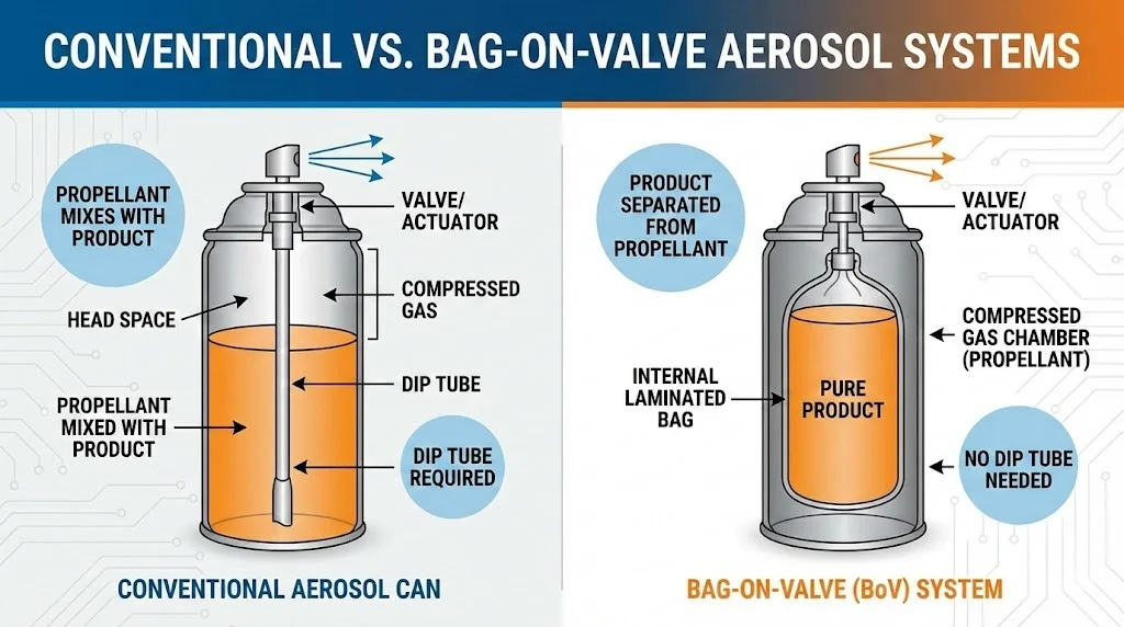
Internal comparison of a conventional aerosol can versus a bag-on-valve (BOV) aerosol system.
How Bag-on-Valve Works
Bag-on-valve technology separates the product concentrate from the propellant gas, using physical pressure on an internal laminated bag to expel the fluid. In bag-on-valve systems, operation is defined by the following characteristics:
- The product is sealed inside a laminated internal bag.
- Compressed gas occupies the space between the bag and the can wall.
- When sprayed, the gas collapses the bag, pushing product out.
The propellant never contacts the product.
Advantages of Bag-on-Valve
- 360° spraying
- No propellant contamination
- Improved product stability
- Suitable for pharmaceuticals, cosmetics, and food
- Reduced flammability risks
Cost and Manufacturing Differences
BOV systems require:
- Specialized valves
- Internal bag insertion
- Higher component cost
However, they offer superior technical performance for sensitive formulations.
Common Engineering and Manufacturing Problems
Maintaining high quality standards in aerosol manufacturing requires a deep understanding of common engineering and performance failures. From low pressure discharges to valve leakages and spray pattern inconsistencies, each issue can trace its roots back to formulation chemistry, hardware matching, or filling defects. Below, we examine these common problems and their technical causes.
Low Spray Pressure
This specific condition is typically caused by several compounding technical factors that compromise the internal pressure, material strength, or chemical stability of the canister:
- Insufficient propellant charge
- Incorrect vapor pressure selection
- Leakage at crimp or gasket
Valve Leakage Issues
Understanding the common causes of these failures is essential for maintaining strict quality control. These issues typically stem from mechanical, metallurgical, or formulation-related factors during production:
- Improper crimp dimensions
- Gasket incompatibility
- Chemical attack from formulation solvents
- Particulate contamination during filling
Inconsistent Spray Pattern
This performance variation typically results from a combination of fluid dynamics, nozzle configurations, propellant ratios, and formulation viscosity characteristics during discharge:
- Actuator orifice blockage
- Improper formulation viscosity
- Inconsistent propellant–product ratio
- Poor internal mixing
Can Bulging and Burst Failures
These critical structural and mechanical failures are directly linked to pressure limitations, material fatigue, assembly errors, and chemical degradation pathways inside the container:
- Overfilling
- Excessive temperature exposure
- Incorrect can specification
- Illegal propellant blends with abnormal vapor pressure
Propellant–Formulation Incompatibility
Formulators must monitor a range of compatibility issues that can emerge during long-term storage under pressurized conditions. These chemical and mechanical issues include:
- Phase separation
- Corrosion of can interior
- Elastomer swelling in gaskets
- Loss of spray efficiency over shelf life
Safety Mechanisms in Aerosol Cans
Aerosol cans are pressurized vessels that require rigorous safety engineering and quality control during design and production. Compliance with national and international standards ensures that canisters can withstand extreme temperatures, transport vibrations, and physical impacts without risk of failure. The following safety protocols are industry-standard mechanisms to guarantee consumer and workplace safety.
Pressure Resistance Testing
To ensure maximum safety and prevent accidental bursts during transport or consumer use, all pressurized canisters must pass strict structural stress tests. Every aerosol design undergoes the following testing protocols:
- Hydraulic deformation testing
- Burst pressure testing
- Hot-water bath testing at elevated temperatures
These ensure a minimum safety margin above maximum working pressure.
Transport and Storage Safety
Aerosols are classified as dangerous goods under international transport codes. Packaging, labeling, and temperature control are strictly regulated.
Indian and Global Standards
Aerosol manufacturing follows:
- BIS standards for pressure containers
- PESO licensing for hydrocarbon storage
- UN transport classification for aerosols
- ADR, IMDG, and IATA rules for export shipments
How Aerosol Working Impacts Product Performance
Spray mechanics directly affect:
- Particle size distribution
- Surface coverage and wetting
- Consumer sensory experience
- Product depletion efficiency
- Shelf stability and propellant retention
Aerosol performance is therefore an integrated result of:
- Formulation chemistry
- Propellant selection
- Valve engineering
- Actuator design
- Can metallurgy
How Startups Can Select the Right Aerosol System
Startups should never treat aerosol packaging as a generic component. Correct system selection requires:
- Matching propellant vapor pressure to required spray force
- Selecting valve flow rate for formulation viscosity
- Choosing actuator geometry for the target spray pattern
- Ensuring chemical compatibility with all elastomers and can coatings
- Balancing cost vs safety vs regulatory acceptance
Incorrect selection at this stage leads to costly reformulation and tooling changes later.
Aerosol Manufacturing in India vs Global Practices
India uses globally accepted aerosol filling technologies:
- Cold filling
- Pressure filling
- Under-the-cup gassing
- BOV filling systems for special products
Indian manufacturers follow international supply chains for:
- Valves (including European and Asian suppliers)
- Actuators
- Propellants
- Beverage-grade and pharmaceutical-grade gases
Export-oriented units additionally comply with EU and US pressure vessel and flammability regulations.
Authoritative External References for Aerosol Technology
For readers who want to explore internationally recognized technical standards and regulatory frameworks related to aerosol technology, the following authoritative external resources provide verified engineering and safety guidance used across the global aerosol industry:
European Aerosol Federation (FEA): The FEA publishes official technical standards, safety
guides, and best practices followed by aerosol manufacturers worldwide, especially across the EU. These
documents form the backbone of many international aerosol safety and performance protocols.
https://www.aerosol.org
United Nations Model Regulations for the Transport of Dangerous Goods: These regulations
define how aerosols are classified, packed, labeled, and transported globally by road, sea, and air. They
are the legal foundation for ADR, IMDG, and IATA aerosol transport rules.
https://unece.org/transport/dangerous-goods
U.S. Food & Drug Administration (FDA) – Aerosol Drug Products: The FDA provides detailed
guidance on aerosol drug delivery systems, valve performance, metered-dose sprays, and pharmaceutical
aerosol compliance requirements.
https://www.fda.gov/regulatory-information/search-fda-guidance-documents/metered-dose-inhaler-mdi-and-dry-powder-inhaler-dpi-drug-products-quality-considerations
Bureau of Indian Standards (BIS): BIS publishes the Indian pressure vessel, aerosol
container, and flammable goods handling standards that legally govern aerosol manufacturing and storage in
India.
https://www.services.bis.gov.in
Petroleum and Explosives Safety Organisation (PESO), India: PESO regulates the storage,
filling, and handling of liquefied petroleum gas (LPG) and other flammable propellants used in aerosol
manufacturing across India.
https://peso.gov.in
Future of Aerosol Technology
Technological development is focused on:
- Ultra-low GWP propellants
- Improved BOV designs
- Precision metered sprays
- Advanced actuator micro-machining
- Lightweight high-strength aluminum cans
Environmental regulation is continuously influencing propellant selection without changing the fundamental physics of aerosol operation.
Complete Aerosol Manufacturing Guidance
For entrepreneurs, formulators, and manufacturers who require step-by-step, plant-level technical
guidance—from product formulation and propellant selection to filling line design, safety compliance,
testing protocols, and commercial scale-up—you can access a complete technical overview here:
/aerosol-manufacturing-101-guide
This resource covers real industrial practices used in FMCG, pharmaceutical, automotive, and industrial aerosol production.
Conclusion: Key Takeaways on How Aerosol Cans Work
An aerosol can operates through the controlled interaction of:
- Stored propellant pressure
- Precision valve sealing and flow control
- Flash atomization in the actuator
- Engineered spray dynamics
The system is entirely driven by thermodynamics and fluid mechanics—not mechanical pumping. Commercial aerosol success depends on correct engineering of all components as a single functional system rather than as individual parts.
Frequently Asked Questions
How much pressure is inside an aerosol can?
Can aerosol cans explode?
Why do some aerosols spray as foam?
What is the safest aerosol propellant?
What does the dip tube do in an aerosol can?
Why does an aerosol can feel cold during use?
Need Technical Support for Aerosol Formulations?
Partner with Global Aerosols to audit, scale up, and troubleshoot your aerosol chemistry, canister pressure calculations, filling lines, and safety systems.
Email: consulting@globalaerosols.com
Website: https://www.globalaerosols.com
Phone: +91 9819548320 +91 8169102990
About the Specialist
Absar Khan is the founder and lead aerosol consultant at Global Aerosols. He possesses cross-disciplinary engineering expertise spanning aerosol valve and propellant engineering, filling line design, pressure and safety compliance, and formulation development. Absar leads scientific and engineering advisory teams supporting manufacturers globally in technology selection, GMP layouts, validation frameworks, and regulatory strategies.
LinkedIn Portfolio: Connect with Absar Khan on LinkedIn